 Programmable Limit SwitchProgrammable Limit Switch
Programmable Limit Switches (PLSs) are used to turn on and off drive digital outputs based on the drive's position. Multiple positions can be combined to affect the state of an output when PLSs are combined.
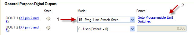
To use PLSs, you must first configure a digital output as follows:
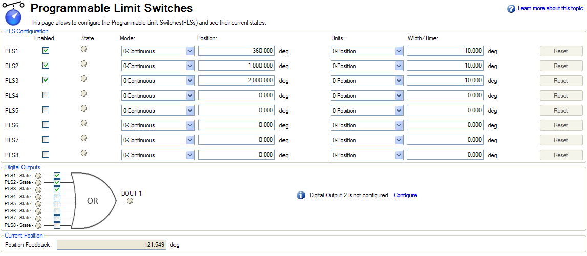
The PLS screen is used to establish the positions for the output(s) to turn on.
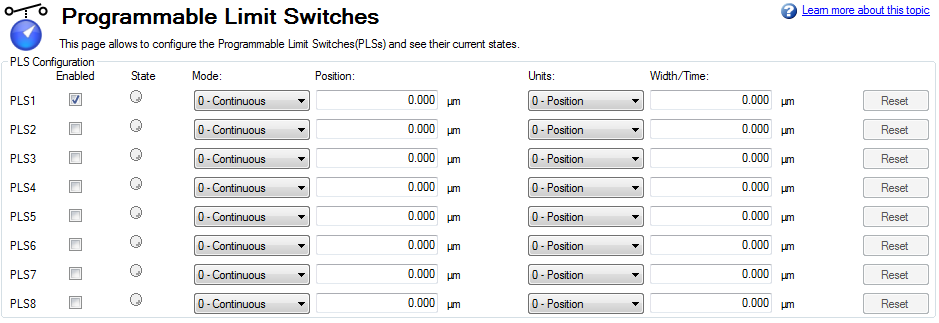
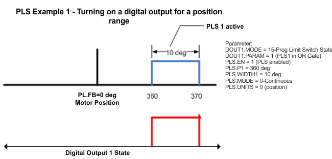
The PLS configuration section of the screen sets the mode and limits of each of the eight PLSs. The PLS is ignored unless it is enabled (see image above). In the screen example, PLS1 is set for continuous operation in position mode. Every time the 360 degree position (PL.FB) is crossed in either direction, the output will turn on for 10 degrees of motor movement.
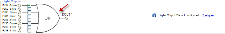
The final step is to configure the OR gate for the PLSs on which output is triggered. The gate appears for setup in the screen when a digital output is configured in Mode 15 – Prog Limit Switch State. Since only PLS1 is configured, select PLS 1 (see arrow above)
To setup an output with multiple turn-on points, configure and enable more PLS’s and include them in the OR Gate.
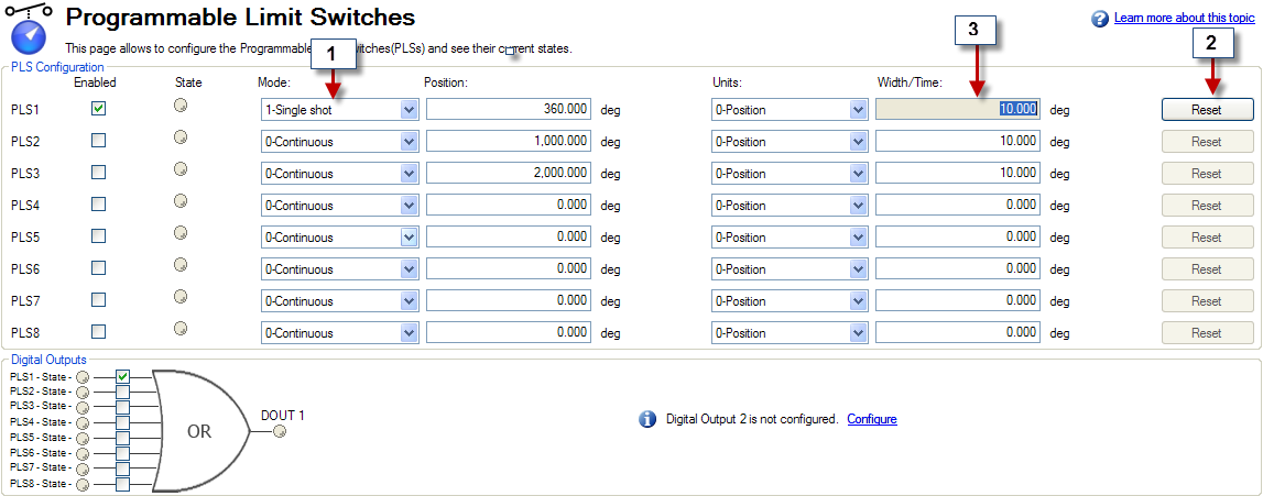
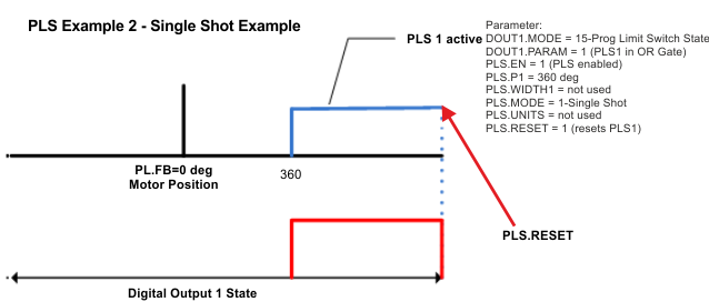
Single shot mode is a special mode of PLS. Single shot mode (see 1 below) turns on the output until it is reset (see 2 below). Normal operation of this mode usually depends on a machine controller to reset the PLS using the fieldbus object for PLS.RESET .
Single Shot Example:
Related Parameters
PLS Parameters and Commands
|
Stay Connected with Kollmorgen       
|
Copyright © 2015 Kollmorgen™ |

|